Finn Sinclair
Building new ways for humans to connect with each other and the objects, machines, and tools they use.
Engineer at  HoloLens
Building new ways for humans to connect with each other and the objects, machines, and tools they use.
Engineer at HoloLens
 18 Jan 2020 - Finn Sinclair
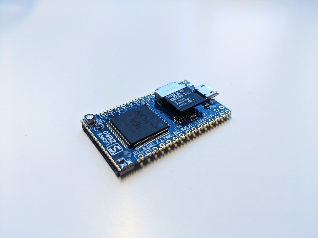
The LicheePi Zero is a lovely, tiny, single-board computer, running on the ubiquitous and low-cost Allwinner V3S platform. Extremely cheap single-board computers have exploded in popularity in recent years, even beyond the (in)famous Raspberry Pi. Other, smaller manufacturers have popped up, designing simple SBCs around inexpensive ARM SoCs. For hobbyists and hackers that want a more hands-on and challenging experience than you’d find with a Raspberry Pi, these cheap SoCs are a great hobby project and weekend adventure.
To add to the already significant challenge, most of the (sparse) documentation is in Chinese, and many of the necessary files are hosted on Chinese sites that are difficult to use or access from the States. While some challenges are technical in nature and can provide some value to the intrepid hobbyist, inaccessible documentation and unresponsive file-sharing sites are not the kind of issues I’d like to let stand. Thus, I wanted to share a guide for my English-speaking friends, serving as a concise tutorial for compiling the Linux kernel, a bootloader, and creating a root filesystem for the board.
One of the main sources of reference for working with Allwinner SoC-based platforms will be linux-sunxi, an open source community that develops software for these low-cost single board computers. They have a great guide for compiling the various components for these boards, and also host a wide variety of repositories containing code specialized for these platforms. We’ll be using their configuration for u-boot, and some of the shell snippets I’ll share are borrowed from their guides.
The bootloader we’ll be using is the popular Das U-Boot, a basic bootloader designed to run on pretty much anything. Because the V3S SoC is well supported, we’ll be able to use the mainline, upstream U-Boot repository, with no need for any specialized Lichee or Sunxi forks.
For the kernel, we’ll be using the LicheePi fork of the Linux kernel. Theoretically, upstream Linux would work just fine, but I can’t find a configuration file for the V3S in the upstream repository. Lichee hosts a fork that includes a configuration file that I’ve found to work well, so we’ll use that. If you figure out the configuration file for the most recent upstream kernel, please let me know, and I can update this! Ideally, we ought to use the upstream versions of both U-Boot and the kernel, but we’ll settle for just using upstream U-Boot for now, and using Lichee’s Linux fork.
You should be using a relatively up-to-date version of Linux on your workstation; it’s possible to do some of this on Windows, but certain tasks like compiling U-Boot and the kernel are much more difficult on Windows. Personally, I try and use WSL for most tasks on my Windows workstation, but even WSL won’t be up to the task today. Either run a VM or create a Linux partition. You won’t need much disk space for this, the minimum disk space allocation should be fine.
The LicheePi Zero is Lichee’s midrange SBC, powered by the Allwinner V3S SoC. The V3S was originally intended for dashcams, but has found a second life as a cheap SoC for hobbyist SBCs! The unit I have here was rougly $12 USD on Aliexpress, with international shipping included. To run Linux at 1.2 GHz, with integrated DDR2, a 3D graphics accelerator, floating point support, 40-pin LCD output, and more, all in the size of a thumb drive, for only $12? Sounds like a deal to me!
The V3S specs are below, as taken from the sunxi wiki:
As a dashcam SoC, it has robust support for H.264 codecs at 1080p, which is quite remarkable for a sub-$5 chip.
You’ll need a few other bits of hardware, too: most importantly, you’ll need some way to talk to the UART on the board. The best way is to use an FTDI breakout board, variants of which are sold literally everywhere and can be found for just a few dollars. We’ll use this as our /dev/ttyUSB0 to talk to our board, both while we are working with the bootloader and when we’re talking to our Linux shell.
Additionally, we’ll be using an MicroSD card (sometimes referred to as a TF card, by some documentation) to flash the bootloader, kernel, and rootfs. The system can support a flash chip, but that’s outside the scope of this tutorial, for now. Some people say that larger-capacity MicroSD cards can cause issues; I’m using an old 8GB Kingston card for this tutorial, which hasn’t given me any issues. If you’re using one with capacity greater than, say, 32GB, and you’re having issues; maybe try a smaller one.
We need to install the compiler toolchain; one pitfall I ran into was that the V3S has hardware floating point support, unlike some other Allwinner chips (F1C100S, for instance). Therefore, we have to be careful to use the gcc-arm-linux-gnueabihf toolchain instead of the gcc-arm-linux-gnueabi toolchain. Install the toolchain like so:
$ sudo apt install gcc-arm-linux-gnueabihf
Make sure that your system is new enough that it downloads at least version >=6.0. U-Boot will not compile without a sufficiently new toolchain. I had to upgrade my ElementaryOS/Ubuntu installation to 18.04 for the included PPAs to have >=6.0.
First step is to compile our bootloader. We’ll be using the mainline, upstream U-Boot distribution, as the V3S is well-supported and requires no extra patches or special support. Clone the U-Boot repository with
$ git clone https://github.com/u-boot/u-boot.git
$ cd u-boot
You may need the swing and python-dev libraries. Install them before proceeding with the U-Boot compilation process.
$ sudo apt install swig python-dev
In order to compile U-Boot for our particular setup, we’ll use the configs/LicheePi_Zero_defconfig that Lichee provides as part of the mainline U-Boot repository we just cloned.
$ make CROSS_COMPILE=arm-linux-gnueabihf- LicheePi_Zero_defconfig
If that works, compile the bootloader:
$ make CROSS_COMPILE=arm-linux-gnueabihf-
If the system complains about not being able to find your toolchain, ensure you included the trailing hypen, as it will use the CROSS_COMPILE environment variable as a prefix to find the rest of the toolchain utilities (gcc, as, ld, etc).
If all goes well, the system should generate a file called u-boot-sunxi-with-spl.bin. This the bootloader binary, and we’ll copy this onto our SD card once we have the rest of the components ready.
Next, we’ll compile the kernel. For this, we’ll need the Lichee fork of the Linux repository; they’ve kindly created a kernel configuration that works well on the board. It would be a long and arduous process to figure out the correct configuration on our own, so we’ll use this configuration for our kernel installation. As the Linux repo is very large with a deep Git history, we’ll do a shallow clone of depth=1 and only clone the particular branch we need:
$ git clone --single-branch --branch="zero-5.2.y" --depth=1 https://github.com/Lichee-Pi/linux.git
$ cd linux
This is the mainline Linux kernel, as of version 5.2, with a few changes; as I mentioned above, they added the configuration file for the LicheePi Zero, as well as the device tree (.dts) file and a useful touchscreen device driver. (We won’t use that in this tutorial, but it’s nice to have anyway.)
Make the configuration by running the following command. This will parse the kernel configuration and generate a .config that the main Make process will use to compile our kernel.
$ make ARCH=arm CROSS_COMPILE=arm-linux-gnueabihf- licheepi_zero_defconfig
If this succeeds, you’re ready to compile your kernel. Make note of how many threads/cores you’d like to assign to the job, and use the -j option to split the workload across them. For example, my system has 8 threads, so I’ll use -j8.
$ make ARCH=arm CROSS_COMPILE=arm-linux-gnueabihf- -j8 all
This will also compile the device tree. In a nutshell, the device’s hardware setup is described in the arch/arm/boot/dts/sun8i-v3s-licheepi-zero.dts file. The compilation process (with make all) will compile the .dts into a compiled, “binary” .dtb file that the bootloader/system can read. We’ll be copying this .dtb file over to our boot SD card, along with the zImage.
We’ll also need to compile/install the kernel modules. In my experience, the device boots fine without performing this step, but kernel modules are important and do need to be copied into the rootfs. Build the modules, and make sure INSTALL_MOD_PATH is set to some empty directory that you can access later. We’ll pull the module tree from this directory later.
$ sudo make ARCH=arm CROSS_COMPILE=arm-linux-gnueabihf- -j8 modules
$ sudo make ARCH=arm CROSS_COMPILE=arm-linux-gnueabihf- -j8 modules_install INSTALL_MOD_PATH=/path/to/some/directory
To automate U-Boot’s boot process, we’ll create a small file that serves as an auto-running script. It contains a few U-Boot commands that will run when U-Boot initializes. Create a file called boot.cmd, containing the following U-Boot commands:
setenv bootargs console=ttyS0,115200 root=/dev/mmcblk0p2 rootwait panic=10
load mmc 0:1 0x43000000 ${fdtfile}
load mmc 0:1 0x42000000 zImage
bootz 0x42000000 - 0x43000000
Because the Sunxi wiki doesn’t explain these whatsoever, I’ll do the honors and break down each command and what purpose it serves.
setenv bootargs console=ttyS0,115200 root=/dev/mmcblk0p2 rootwait panic=10
This line sets the boot arguments, essentially a few short arguments we pass to the booting kernel to initialize a few options. To ensure the boot process outputs to the correct UART, we set the boot argument console=ttyS0,115200. This will ensure the critical boot debugging information is passed to UART0 at 115200 baud. This is usually what it would default to anyway, but it’s nice to be sure. root=/dev/mmcblk0p2 sets the root of the filesystem to the second partition of the SD card. This will become more clear later, but the second partition is the ext4 partition onto which we will load the actual rootfs (OS filesystem). rootwait ensures the boot process will stall and wait for the root storage medium to respond. This is important if the storage is being a bit slow. panic=10 tells the boot process to reboot/retry booting after 10 seconds if the kernel panics during boot.
load mmc 0:1 0x43000000 ${fdtfile}
load mmc 0:1 0x42000000 zImage
These commands load the .dtb file and zImage into memory from the SD card. The 0:1 identifier indicates we’re loading from mmc0, and we’re loading from the first (boot) partition. The .dtb file will be loaded into 0x43000000, and the kernel image will be loaded into 0x42000000. These are relatively arbitrary locations; they’re recommended for most of the Allwinner SoCs, but some use different load addresses. (For instance, the trimmed-down F1C100s SoC needs a high memory address like 0x80000000 and 0x80c00000 to load correctly.)
Finally, the bootz command boots the kernel, with three arguments specified; first, the kernel location, secondly, an option argument for the initramfs that we’re not using, and thirdly, the location of the .dtb file.
Once you’ve created the boot.cmd file with these commands, we’ll format this file into a .scr binary script file that U-Boot can use. Run the command:
$ mkimage -C none -A arm -T script -d boot.cmd boot.scr
The boot.scr file is what we’ll actually copy onto the SD card; boot.cmd will not be used.
The “rootfs” is the filesystem that is actually used by the operating system; it contains pretty much everything the operating system needs to provide the user (or root, in this case) with all the creature comforts that one expects while using a Linux system. It will contain binaries of common applications, like text editors, system utilities, as well as system files and programs.
There are several ways to create a rootfs. I’ve only had success with two methods, but that’s mostly due to my inexperience, rather than an actual technical limitation. The best method I’ve found is to use the excellent Buildroot utility to create a BusyBox-based rootfs that contains trimmed down versions of common Linux utilities. This is best suited for extremely resource-constrained systems; it won’t give you more advanced functionality like a C compiler, package management, or other features. However, the build process is painless, self contained, and relatively idiot-proof, lending itself well to a beginner’s tutorial.
Download the latest stable release of Buildroot, extract, and install the application.
We’ll select a few options for our Buildroot configuration. Run the menu-based configurator.
$ make menuconfig
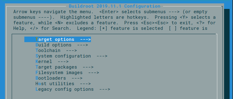
Select the following options. If something else catches your eye, and you don’t think it would interfere with your system, feel free to select that too.
| Config option | Value |
|---|---|
| Target options –> Target Architecture | ARM (little endian) |
| Target options –> Target Architecture Variant | cortex-A7 |
| Target options –> Target ABI | EABIhf |
| Target options –> Floating point strategy | VFPv4 |
| System configuration –> System hostname | Whatever you’d like! |
| System configuration –> System banner | Whatever you’d like! |
| System configuration –> Enable root login with password | Check if you’d like to secure the root login. |
| System configuration –> Root password | If you checked the above, this is the password to the root account. |
One particular area of note are the options for the included Busybox utilties. Busybox provides a set of commonly used utilities, but some are provided optionally.
A few that I’d like to recommend:
| Utility | Description |
|---|---|
Target packages –> Interpreter languages and scripting –> micropython |
A simplified Python interpreter for embedded machines |
Target packages –> Shell and utilities –> file |
Returns information about a file |
Target packages –> Shell and utilities –> screen |
Allows for switching between multiple managed terminal jobs |
Target packages –> Shell and utilities –> ranger |
An improved file manager; requires additional toolchain support, though |
Target packages –> System tools –> htop |
An improved process viewer/manager |
Target packages –> Text editors and viewers –> nano |
A popular editor; requires wchar support |
| Target packages –> Games –> * | Install a few games for fun! |
Once you’ve configured the Buildroot system with your favorite BusyBox utilities, build the filesystem:
$ make
Yes, it’s really that simple. This will take a good while (especially on slower systems), so, make a cup of tea, relax, and come back later. A few interesting notes while you’re waiting:
Once the lengthy build process is complete, you’ll have a rootfs.tar file in your output folder. This is what we’ll un-archive into our SD card.
We need to prep the card for use as a boot medium. Most of this is directly from the wonderful Sunxi bootable SD card guide, but I’ve edited it down to the steps that we need to perform for our project.
First, we need to mount and clean the SD card. Safe to say, anything on the card previously will be wiped, so please don’t use a card that is precious to you! If you’re used to working with removable storage on Linux, this will be old news, but here’s the boilerplate commands anyway.
The commands are slightly different depending on whether you’re using a USB-based external card reader, or an internally mounted MMC reader. I’m using a USB card reader, so when I run sudo fdisk -l to view the connected storage devices, I see my SD card as /dev/sdb. If you’re using a USB reader too, you’ll see your card as /dev/sdX, where X is some letter, depending on your configuration and if other SD devices are connected.
Make sure you identify the correct device. If you accidentally choose the incorrect device, you can permanently destroy data on another device, and irreversibly lose your information.
Once you’ve identified your device, export the name as as shell variable for easy use later.
$ export card=/dev/sdX
If the card is connected as a raw MMC device, it will probably appear as /dev/mmcblk0. Thus, export the variable as such:
$ export card=/dev/mmcblk0
Wipe the card’s partition table with the following command:
$ sudo dd if=/dev/zero of=${card} bs=1M count=1
If you’re not familiar with dd, the bs option indicates we’ll be writing a block of size 1M, and count=1 indicates we’ll be writing a single 1M block. if is the input, which will be /dev/zero as we’re zeroing out the partition table, and of is the output, which is our SD card. (Basic stuff, but still important.)
Next, we write the bootloader binary onto the device. Locate the u-boot-sunxi-with-spl.bin file we created earlier.
$ sudo dd if=/path/to/your/binfile/u-boot-sunxi-with-spl.bin of=${card} bs=1024 seek=8
Again, we’re using dd similarly as before, but this time our input is our .bin file, and we’re seeking 8 1024-byte blocks into the card, because the bootloader needs to start at 8K into the memory region of the card.
Next, we need to create a few partitions; notably, we’ll make a small boot partition that will hold our kernel zImage, the device tree binary, and the boot script.
.dtb file we generated earlier. It’s placed alongside the kernel image in the boot partition.The layout of these partitions and the files within:
| Partition | Contents |
|---|---|
| Boot partition (VFAT) (mmc 0:1) | zImage, boot.scr, sun8i-v3s-licheepi-zero.dtb |
| Root partition (EXT4) (mmc 0:2) | Extracted/un-archived root filesystem |
To create these partitions, we’ll use blockdev, which is a utility for controlling block devices, and sfdisk, a partition table utility.
$ sudo blockdev --rereadpt ${card}
$ cat <<EOT | sudo sfdisk ${card}
1,16,c
,,L
EOT
For those unaware, the sfdisk command behaves a little weirdly; you’ll type in the partition formatting after you run the second command, but they’re not commands: sfdisk just expects the formatting data as part of its standard input.
Creating the filesystems themselves is slightly different depending on whether you’ve mounted the SD card through a USB reader or as an MMC block device, so, only execute the one command that is relevant to your system.
$ mkfs.vfat ${card}p1
$ mkfs.ext4 ${card}p2
$ mkfs.vfat ${card}1
$ mkfs.ext4 ${card}2
Now that we have the partitions created, and the filesystems created within, it’s time to copy our files onto these filesystems. First, we mount the SD card’s boot partition to our host system. Again, the device name is slightly different depending on whether you’re using a USB reader or not; only execute one of these commands.
$ sudo mount ${card}p1 /mnt/
$ sudo mount ${card}1 /mnt/
Then, we copy our files to the boot partition.
$ sudo cp /path/to/your/linux/repo/arch/arm/boot/zImage /mnt/
$ sudo cp /path/to/your/script/boot.scr /mnt/
$ sudo cp /path/to/your/linux/repo/arch/arm/boot/dts/sun8i-v3s-licheepi-zero.dtb /mnt/
Then, sync all changes and unmount the SD card.
sync
sudo umount /dev/
At this point, you can actually remove the SD card, place it in your device, and boot to the bootloader! It’ll fail to boot the OS, of course, as we haven’t copied the rootfs yet, but it would be a good smoketest. Skip to the “FTDI/UART” section if you’d like to test this.
Next, we can mount the main ext4 partition and copy the rootfs we created.
$ sudo mount ${card}p2 /mnt/
$ sudo mount ${card}2 /mnt/
The rootfs that we built with Buildroot should be in the /path/to/your/buildroot/output/images folder. Remove it from the .tar and copy it to the SD card with:
$ tar -C /mnt/ -xf images/rootfs.tar
Inspect the SD card and verify that the root filesystem has been correctly extracted. Running ls /mnt/ should return something that looks generally like this:
bin  etc  lib32    media  opt   root  sbin  tmp  var
dev  lib  linuxrc  mnt    proc  run   sys   usr
If not, remove everything in the SD card (sudo rm -rf /mnt/*) and try again.
Next, we’ll copy over the kernel modules we compiled earlier. Recall the directory you compiled them into, and run the following commands:
sudo mkdir -p /mnt/lib/modules
sudo rm -rf /mnt/lib/modules/
sudo cp -r <YOUR_MODULE_DIRECTORY>/output/lib /mnt/
The rm -rf will simply clean the existing /mnt/lib/modules folder if one exists. If you’ve been following the tutorial, the rootfs we built with Buildroot does not include any in the image; so this is unnecessary. However, if you were using some other rootfs from some other source, there may be some pre-existing files. Removing them will provide a clean slate for us.
The rootfs copying process is now done! If everything worked correctly, you should now have a fully functioning SD card for your device.
Sync and unmount the SD card when you’re done.
sync
sudo umount /dev/
The time has come; we can now boot our system and see the fruits of our effort. Plug in and install your FTDI breakout (or other serial adapter solution) on the workstation. We’ll be using minicom as a feature-rich and easy-to-use serial monitor; there are a plethora of other ways to talk to a serial port, but I’ve found minicom to be excellent. Install it with your package manager of choice if you don’t already have it.
Run minicom and configure the terminal to use /dev/ttyUSB0 (for an FTDI breakout) with 115200 baud, 8N1, with no hardware flow control or software flow control. You can access the minicom serial configuration menu by pressing ctrl-A, then Z, after running it. Open the configuration with O, navigate to “Serial port setup” and verify your serial settings look like the picture.
+------------------------------------------+
| A -    Serial Device      : /dev/ttyUSB0 |
| B - Lockfile Location     : /var/lock    |
| C -   Callin Program      :              |
| D -  Callout Program      :              |
| E -    Bps/Par/Bits       : 115200 8N1   |
| F - Hardware Flow Control : No           |
| G - Software Flow Control : No           |
|                                          |
|    Change which setting?                 |
+------------------------------------------+
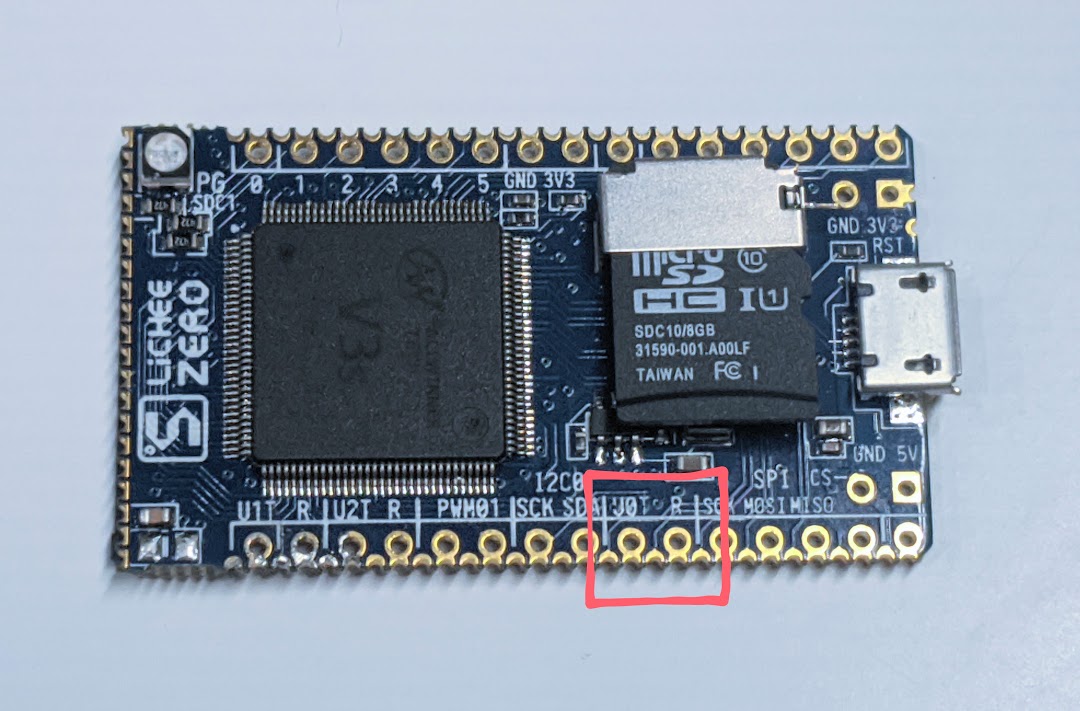
Once the serial port has been configured, connect your serial adapter to the board. Look for the pins labeled U0T and R. These are the Tx and Rx pins, respectively, of the default UART0. Connect the serial adapter (Tx to Rx, and Rx to Tx), and plug the LicheePi Zero into USB power.
If everything is normal, you should first see the U-Boot terminal briefly, before it auto-boots into our system. You should see a string of kernel boot messages, before you’re dumped to a root terminal.
If you’d like to sanity check your boot logs against what I have, please see this Gist. This is what my LicheePi Zero spits out on boot, using the kernel, U-Boot, and rootfs described in this tutorial.
Have fun with your Busybox environment! You can set a fun message of the day (displayed on bootup) by creating a file in /etc/motd. The popular editor vi should be installed by default, but it is a stripped down version and does not include most of the creature comforts you’d expect from a full vi installation. Explore the filesystem, play some games, write some Micropython scripts, and practice your shell scripting skills. One fun exercise is to run a script or program and use top or htop (if you included it in the Busybox configuration) to inspect how much system resources are being used.
GPIO support is included, which allows you to play with the RGB LED mounted on the board. I wrote a small shell script that illustrates how to enable the GPIO, and write various values. If your board is configured similarly to mine, this should cause the RGB LED to flash different colors for an entertaining light show. GPIOs 192, 193, and 194 are the three color channels of the LED.
#!/bin/sh

echo 192 > /sys/class/gpio/export
echo 193 > /sys/class/gpio/export
echo 194 > /sys/class/gpio/export

echo out > /sys/class/gpio/gpio192/direction
echo out > /sys/class/gpio/gpio193/direction
echo out > /sys/class/gpio/gpio194/direction

for i in $(seq 1 1000);
do
        echo 0 > /sys/class/gpio/gpio193/value
        sleep 0.08
        echo 1 > /sys/class/gpio/gpio193/value
        echo 0 > /sys/class/gpio/gpio194/value
        sleep 0.08
        echo 1 > /sys/class/gpio/gpio194/value
        echo 0 > /sys/class/gpio/gpio192/value
        sleep 0.08
        echo 1 > /sys/class/gpio/gpio192/value
done
For extra fun you can make this a startup script, so that you can impress your friends and family (not really, who am I kidding) with your script without needing to log in. (Run this on the LicheePi, of course.)
First, mark the script as executable (you probably already did this)
$ chmod +x /path/to/your/script/your_script
At the end of the file named rcS in /etc/init.d, append the line
./path/to/your/script/your_script &
Save the file and restart the device. Your script should now begin running, even before root logs in. If your script was my blinky script above, you should be able to see the wonderful blinky lightshow immediately.